Departures from Ideal Performance for Conical Nozzles
and Bell
Nozzles, Straight-Cut Throats and Rounded Throats
High Power Rocketry Magazine; October 2004 and November 2004
Author: Charles E. Rogers (CRogers168@aol.com)
This article covers departures from ideal performance for conical nozzles and bell nozzles, straight-cut throats and rounded throats; including nozzle thrust coefficient losses, and losses from the theoretical specific impulse to delivered specific impulse. Simple design modifications for straight-cut throats are presented which have the potential to increase the thrust, total impulse and specific impulse of most high power solid rocket motors, and almost all experimental/amateur solid rocket motors by 3.5% to 8%, a significant across-the-board increase in performance for two entire classes of rocket motors. The article contains extensive experimental test data, both for professional solid rocket motors and from instrumented tests of high power and experimental/amateur solid rocket motors. The experimental data, and the models based on the experimental data for performance losses from straight-cut throats are unique, and to the author’s knowledge the first published anywhere.
Please note that there was an error in Equation 7 on Page 27 of the first part of this article. There is a formal Errata note at the end of the second half of the article with the corrected Equation 7.
Summary and Key Technical Results and Conclusions from the Article:
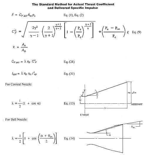
1) The author derives and proposes the Standard Method for correcting the ideal thrust coefficient and the theoretical specific impulse to the actual thrust coefficient and the delivered specific impulse. The key summary equations are presented in the figure below.

Copyright ©2004 by
Charles E. Rogers.
All rights reserved. Used with
permission.
Where:
| Ae = exit area, m2 (in2) | p¥= atmospheric pressure, Pa (lb/in2) | |
| Ath = nozzle throat area, m2 (in2) | a = nozzle divergence half angle, deg | |
| C 0F = ideal thrust coefficient, dimensionless | e = nozzle expansion area ratio, dimensionless | |
| CF ,act = actual thrust coefficient, including all nozzle losses, dimensionless | g = ratio of specific heats, dimensionless | |
| F = thrust, N (lb) | hF = CF efficiency factor, dimensionless | |
| I 0sp = theoretical specific impulse, sec | hq = c* efficiency factor, dimensionless | |
| Ispd = delivered specific impulse, sec | l = nozzle divergence correction factor, dimensionless | |
| pc = chamber pressure, Pa (lb/in2) | qex = nozzle exit plane lip angle, deg | |
| pe = nozzle exit pressure, Pa (lb/in2) |
2) To the author’s knowledge at the time of the writing of the article, with the exception of some of the author’s internal-use computer programs, every solid rocket motor, hybrid rocket motor, and liquid rocket engine computer program, software, spreadsheet, performance charts, etc., for predicting performance and calculating thrust from chamber pressure used by model, high power, and experimental/amateur rocketeers is based on simply multiplying the ideal thrust coefficient by the nozzle divergence correction factor to obtain the actual thrust coefficient.
CF ,act = l C 0F
Which is equivalent to assuming that the CF efficiency factor (hF) is equal to 1.0. All of these computer programs, software packages, spreadsheets, performance charts, etc., can be easily updated to the Standard Method by simply multiplying the ideal thrust coefficient (C 0F) and the nozzle divergence correction factor (l) with the CF efficiency factor (hF).
CF ,act = l hF C 0F
The article presents models for the CF efficiency factor for straight-cut throats (both high performance and low performance) and for rounded throats. These CF efficiency factor models can be retrofitted into existing computer programs, software packages, spreadsheets, etc., using the above equations.
3) Many high power and experimental/amateur rocketeers run programs such as PROPEP, or the USAF ISP code, and assume that the theoretical specific impulse predicted by the program for their propellant will be the specific impulse for their rocket motors using the propellant. Based on the Standard Method delivered specific impulse equation
Ispd = l hF hq I 0sp
This is equivalent to assuming that the nozzle divergence correction factor (l) = 1.0, the CF efficiency factor (hF) = 1.0, and the c* efficiency factor (hq) = 1.0. Even if correct values for the nozzle divergence correction factor and the CF efficiency factor are used, representative values for the c* efficiency factor are still required.
Simply put the theoretical specific impulse is what comes out of programs such as PROPEP and the USAF ISP code. The delivered specific impulse is what the motor will actually deliver. The article provides details on how to make the corrections to the theoretical specific impulse to get the actual delivered specific impulse for a solid rocket motor.
Smaller, shorter solid rocket motors using aluminized or metallized propellants will have lower residence times in the motor, thus reduced combustion efficiency, and hence producing a lower c* efficiency factor. Larger motors are more efficient than smaller motors, due to increased residence times, proportionally less heat transfer into the motor case and nozzle, and proportionally smaller boundary layers for lower boundary layer losses. Thus for any given propellant it is important to track the variation of the c* efficiency factor with motor size.
Based on representative data presented in the article, as the solid rocket motor size is increased from 1 lb propellant weight the delivered specific impulse can be increased by 5% for 50 lb propellant weight motors, and 7.5% for 350 lb propellant weight motors.
4) For the first time to the author’s knowledge, thrust coefficient losses from using straight-cut throats for high power and experimental/amateur solid rocket motors have been quantified. The thrust coefficient losses were much higher than most high power and experimental/amateur rocketeers probably would have expected. While most high power and experimental/amateur rocketeers have performed thrust coefficient calculations assuming no losses beyond divergence losses (equivalent to a CF efficiency factor (hF) = 1.0), the actual thrust coefficient loss from using a straight-cut throat was found to be approximately 10% (a CF efficiency factor (hF) = 0.90) for the straight-cut throat lengths used on most high power and experimental/amateur rocket motors. While the results were primarily based on historical Thiokol solid rocket motor nozzle thrust coefficient data, static firings with chamber pressure measurements for determining experimental values for thrust coefficient were also performed for a large high power solid rocket motor and a large experimental/amateur solid rocket motor, the test results from which confirm the trends from the historical Thiokol data.
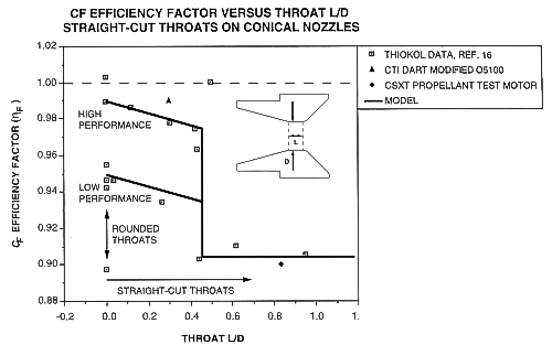
5) Most high power and experimental/amateur rocketeers, beyond expecting thrust coefficient losses from straight-cut throats to be small, probably expected a somewhat linear variation of thrust coefficient loss with straight-cut throat length. A surprise finding from the CF efficiency factor results was a definite jump in the CF efficiency factor, and hence the nozzle thrust coefficient as the straight-cut throat L/D was reduced to less than 0.45. The summary plot of CF efficiency factor versus straight-cut throat L/D is presented below, which graphically shows the jump in CF efficiency factor when the straight-cut throat L/D is less than 0.45.

All rights reserved. Used with permission.
The CF efficiency factor models developed from the historical Thiokol data and the experimental data from the high power and experimental/amateur solid rocket motor static firings, all of which are plotted in the figure above, are as follows:
For Conical Nozzles with Straight-Cut Throats:
CF ,act = l hF C 0F
For Throat L/D < 0.45
High Performance:
hF = 0.99 - ( 0.0333 * L/D )
Low Performance:
hF = 0.95 - ( 0.0333 * L/D )
For Throat L/D ³ 0.45
hF = 0.905
For Conical Nozzles with Rounded Throats:
CF ,act = l hF C 0F
hF = 0.99 (high performance) to hF = 0.95 (low performance)
6) From the above models it’s clear that if the nozzle designer can get the throat L/D of the straight-cut throat under 0.45, there will be a large (3.5% to 8%) jump in performance. Based on this result, the author recommends the following throat design criteria for conical nozzles with straight-cut throats:
Throat Design Criteria for Conical Nozzles with Straight-Cut Throats:
Throat L/D £ 0.40
A throat L/D £ 0.40 is used rather than a throat L/D < 0.45, to provide extra margin to be sure that the jump in nozzle performance indicated by the models based on the historical Thiokol data and the high power and experimental/amateur solid rocket motor experimental data, as shown in the plot of CF efficiency factor versus straight-cut throat L/D presented above, is achieved.
If there is a single conclusion that the reader should come away with from reading the article, it is that on straight-cut throats to make sure that the throat L/D £ 0.40.
7) Based on the CF efficiency factor models presented above which are based on the historical Thiokol data and the high power and experimental/amateur solid rocket motor experimental data, in the article the author proposes two high-performance nozzle designs using straight-cut throats. The first nozzle is an “optimal” very high performance design using a shorter length straight-cut throat and a well-rounded throat entrance, but which can only be drilled for throat area adjustments to a limited degree.The second nozzle is a “universal” nozzle design with the straight-cut throat length short enough to meet the throat L/D design criteria and get the jump in performance indicated by the CF efficiency factor models presented above, with no throat entrance rounding, but with the ability to be drilled to a wide range of throat areas while still maintaining the same throat entrance profile (a sharp throat entrance). Performance predictions for the “optimal” and “universal” nozzles are presented based on the CF efficiency factor models and calculated nozzle divergence correction factor.
This article was Parts 4 and 5 of The Solid Rocket Motor series of articles.
Other articles in The Solid Rocket Motor series:
Performance Analysis of the Ideal Rocket Motor, January 1997
Parts 1 and 2
Solid Propellant Selection and
Characterization, February (A) 2001 and February (B) 2001
Part 3
Solid Propellant Grain Design and Internal
Ballistics, October/November 2002
Parts 4 and 5
Departures from Ideal Performance for Conical
Nozzles and Bell Nozzles, Straight-Cut Throats and Rounded Throats,
October 2004 and November 2004
Part 6
Erosive Burning Design Criteria For High Power and
Experimental/Amateur Solid Rocket Motors, January 2005